I’m going to write up some details on the trouble I’m experiencing with my controller design. I’m planning to ask experienced people for advice and once the problem gets solved (hopefully) I’ll share the solution for the public benefit 🙂
OK, what is the trouble?
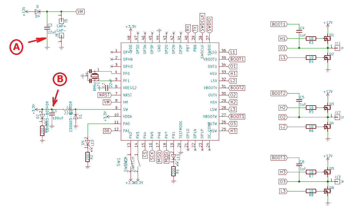
I’m trying to drive powerful 3-phase BLDC motor using MCU. I use STSPIN32F0 which has integrated MOSFET drivers and integrated 3.3V buck converter. I use timers to generate 3-phase sinusoidal PWM. My problem is that high-current components don’t coexist nicely with 3.3V logic on the same small board. If I drive motor very gently, it is all good, but as I increase power interference on power line and on ground gets so high that debugging interface stops responding and MCU resets. KiCad project can be found here.
OK, show me some photos!
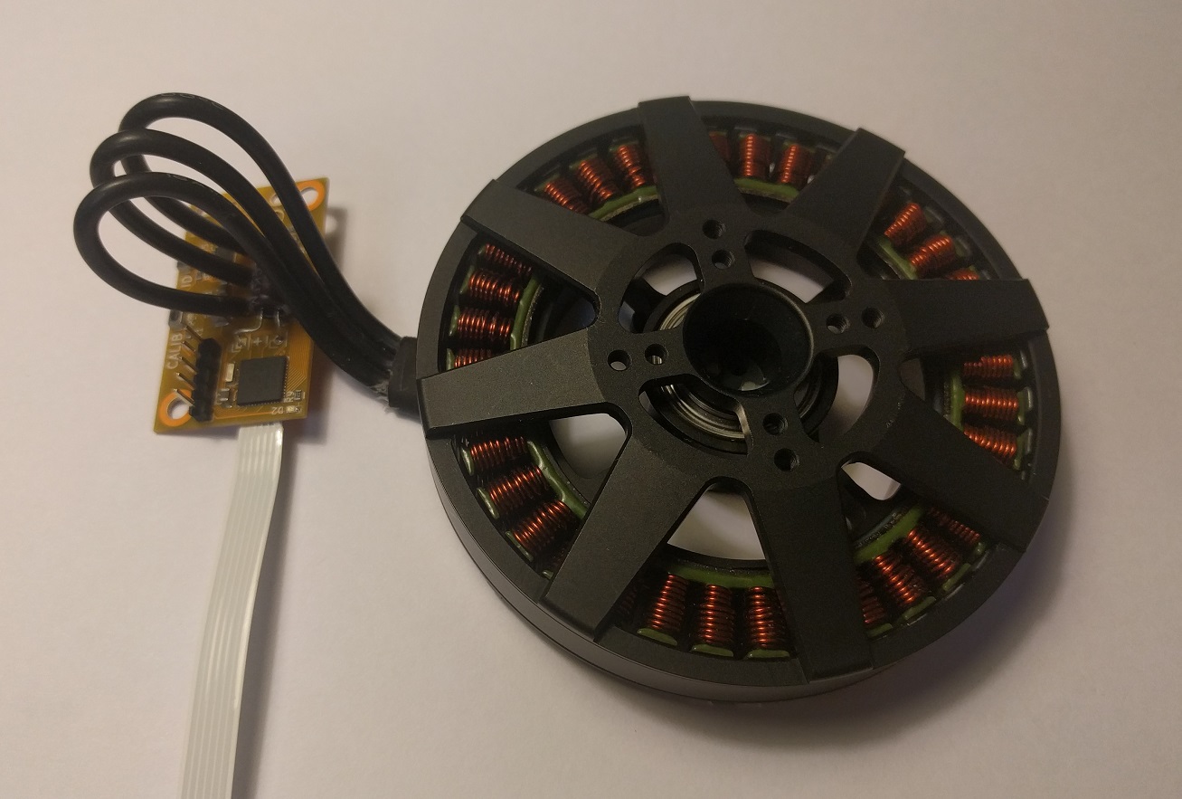
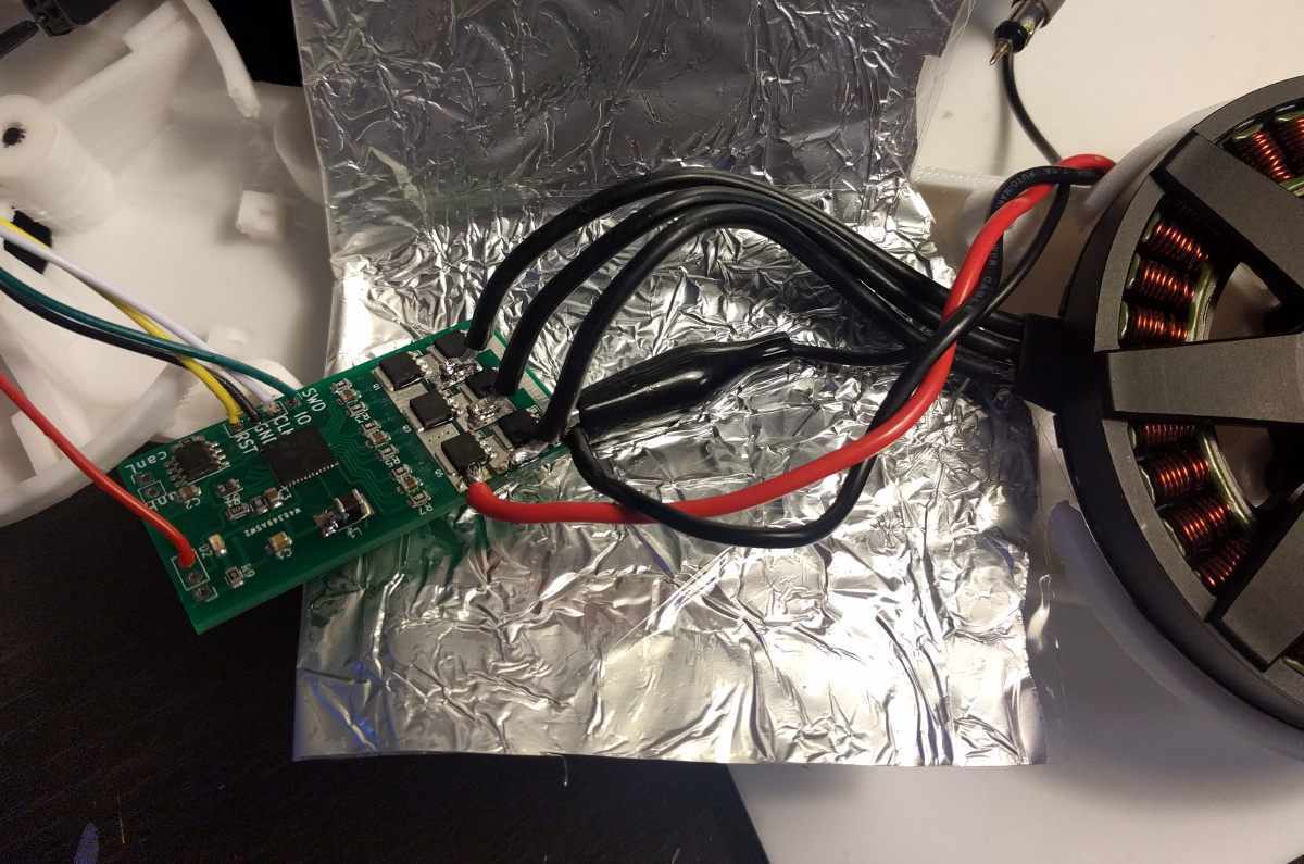
This is to give you the idea of the size of the motor: it is 9cm in diameter. Winding resistance is 0.1 Ohm, and resistance of MOSETS is 0.002 Ohm.
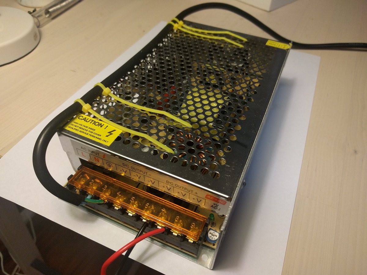
Power supply is 12V 20A rated
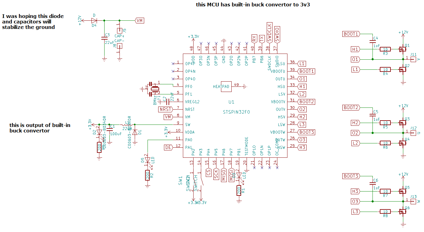
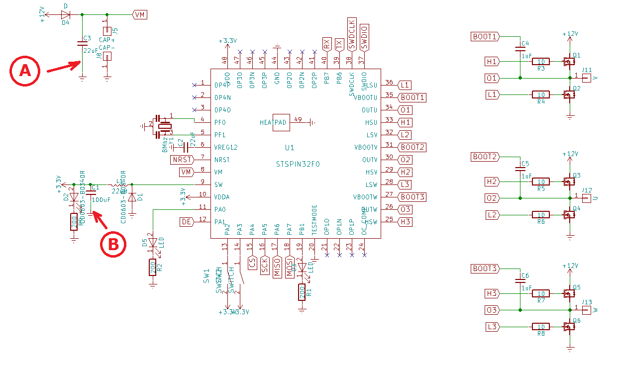
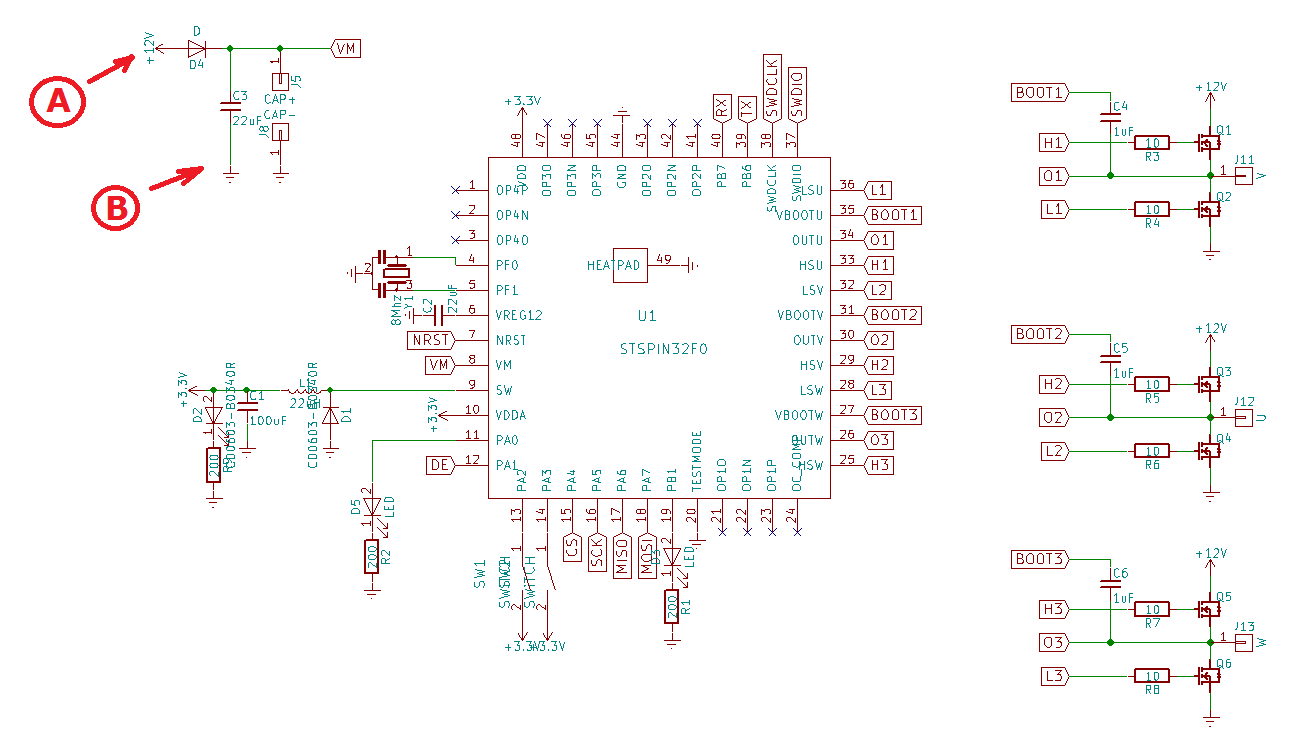
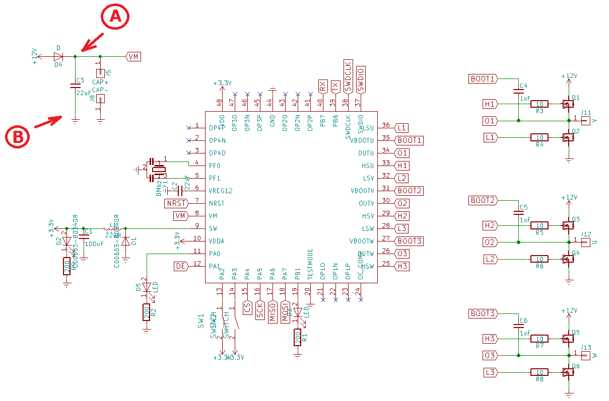
This is the relevant piece of schematic
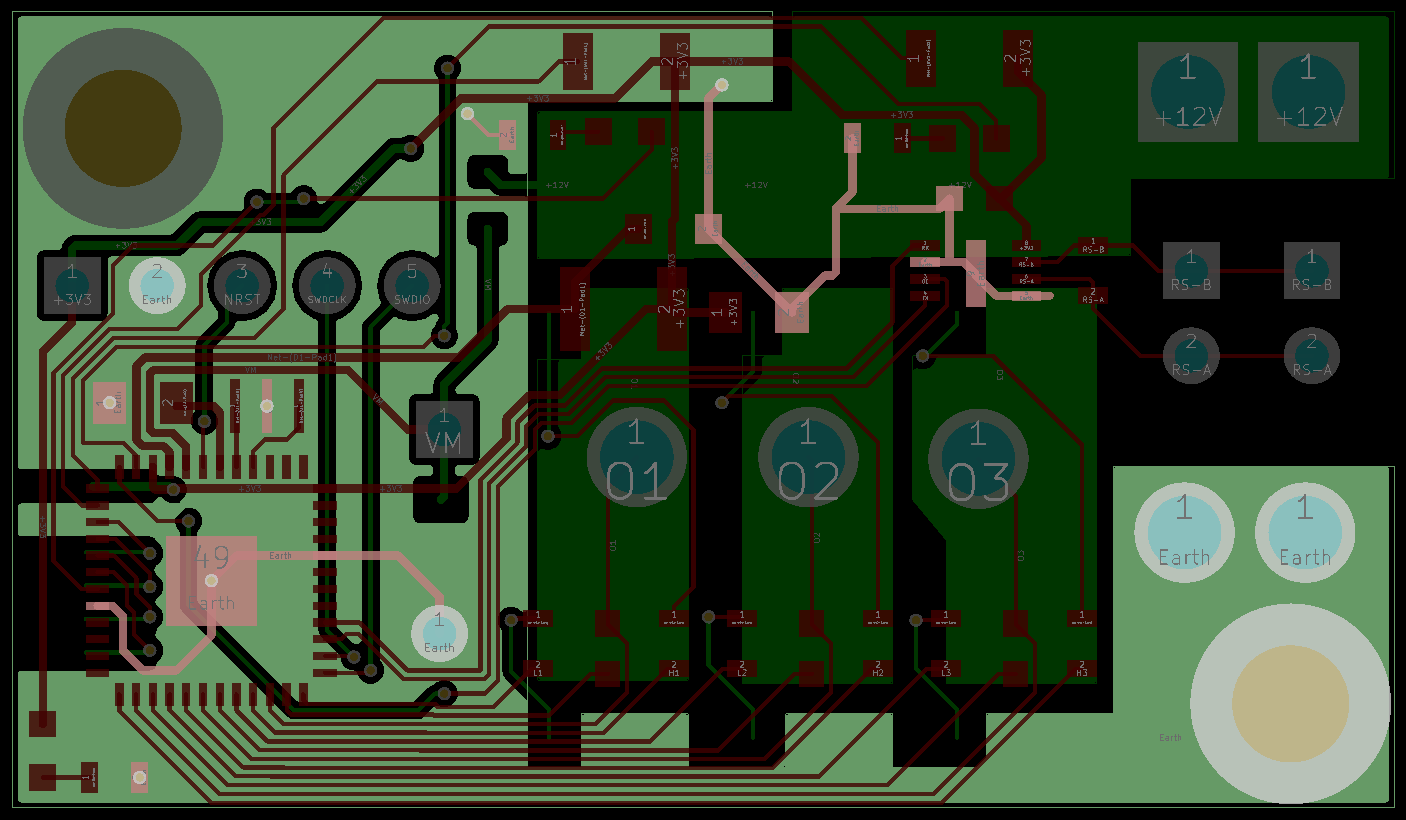
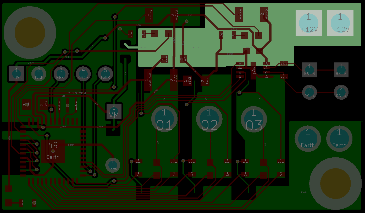
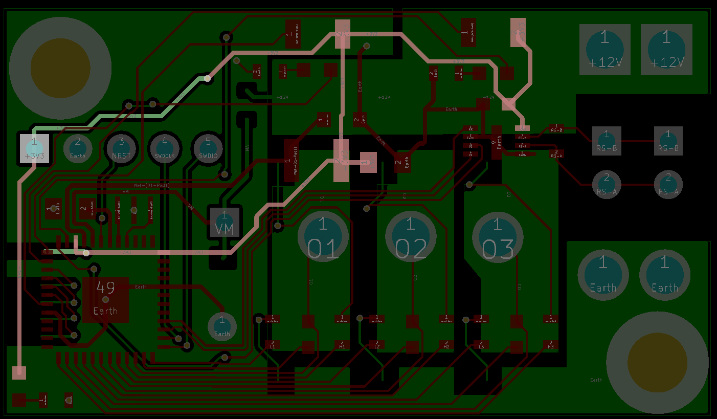
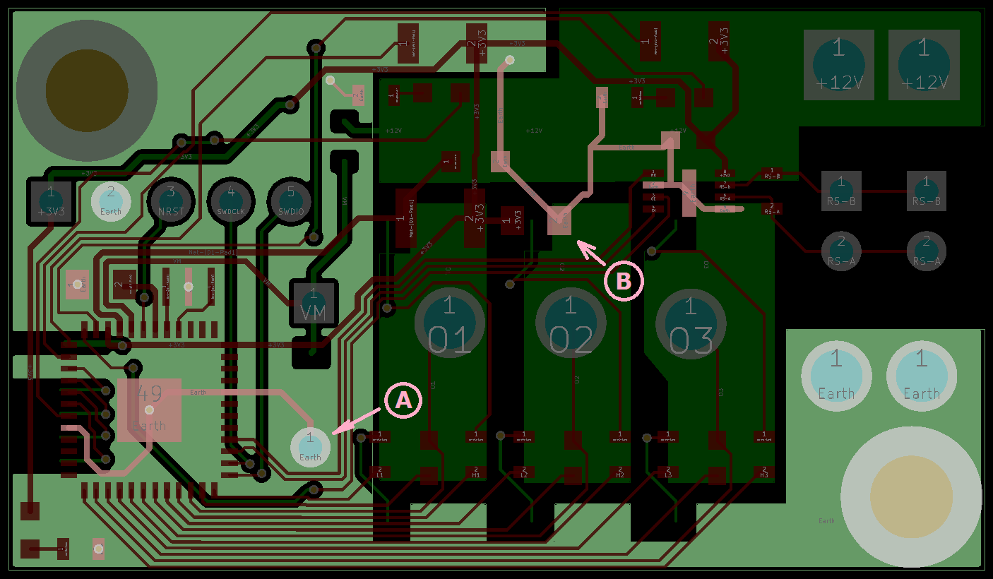
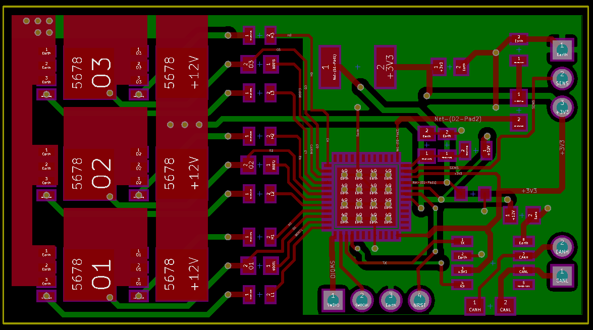
And PCB
| Ground tracks – top and bottom layers | 12V only on bottom layer | 3.3V |
 |
 |
 |
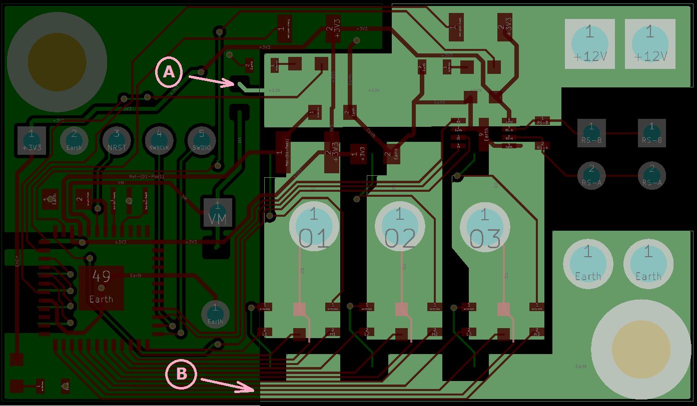
These are high-current tracks. Beyond points A and B only low-current digital logic.
So what kind of interference do you see?
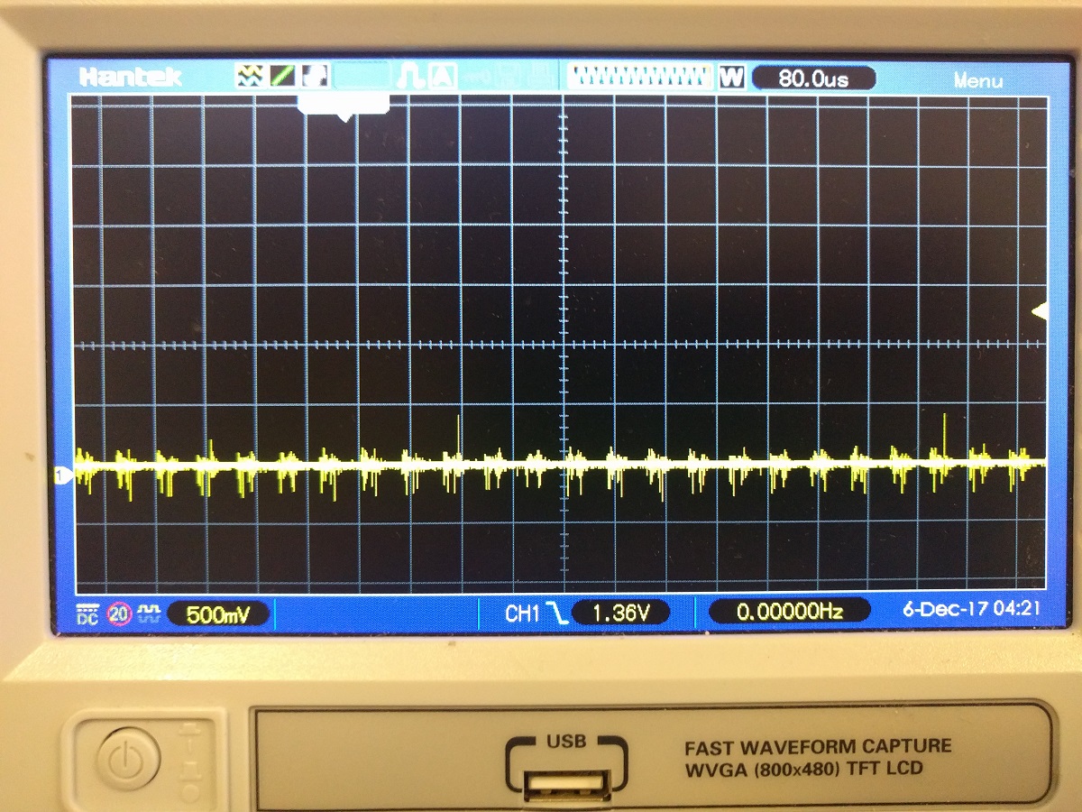
Using PWM I can control how much power I push though the motor and this is what I get when I push about 20%. More than 20% is not possible because MCU stops responding to debugger and occasionally resets.
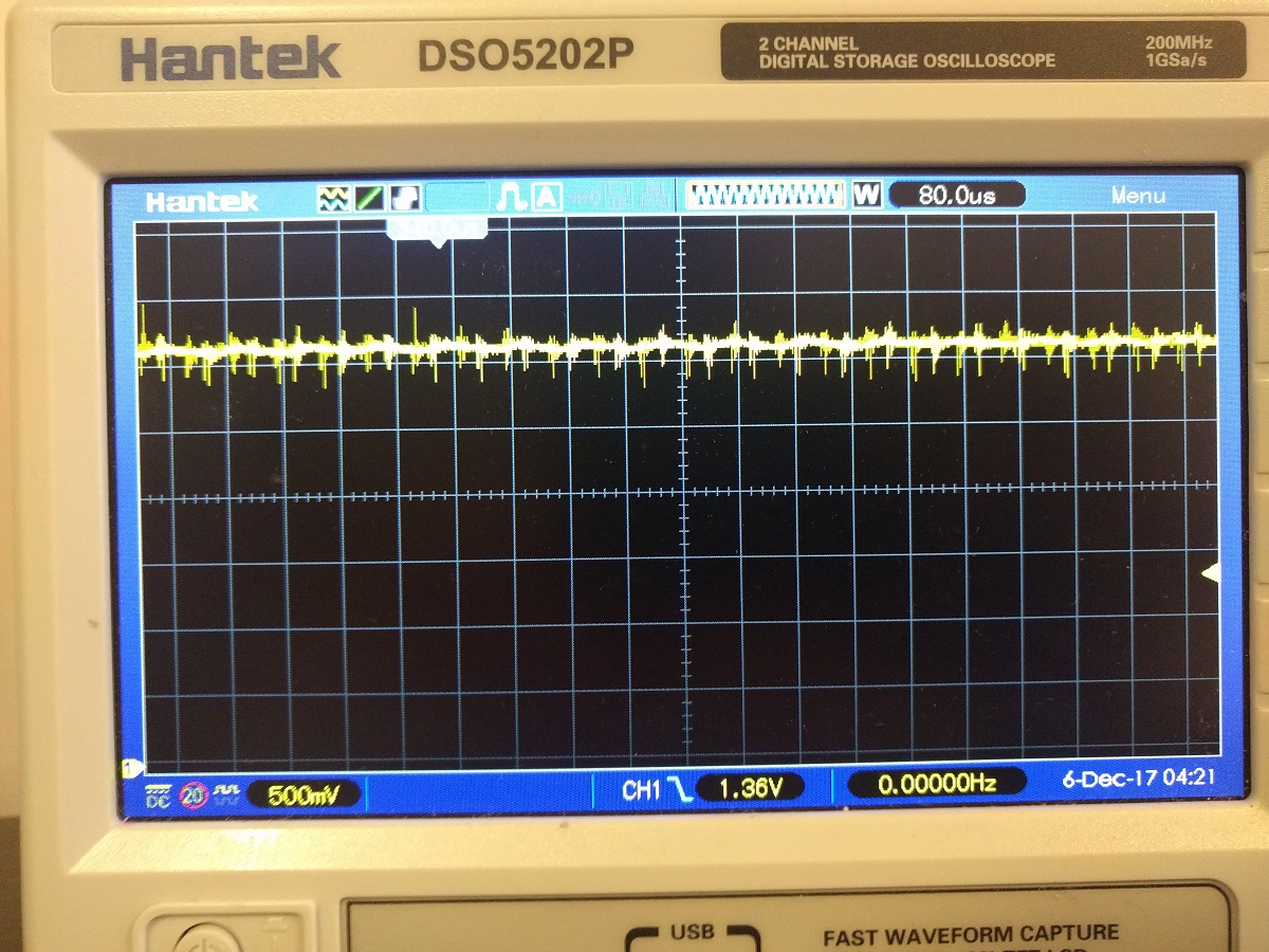
Instead of nice straight zero this is what I see between two ground points:
 |
 |
 |
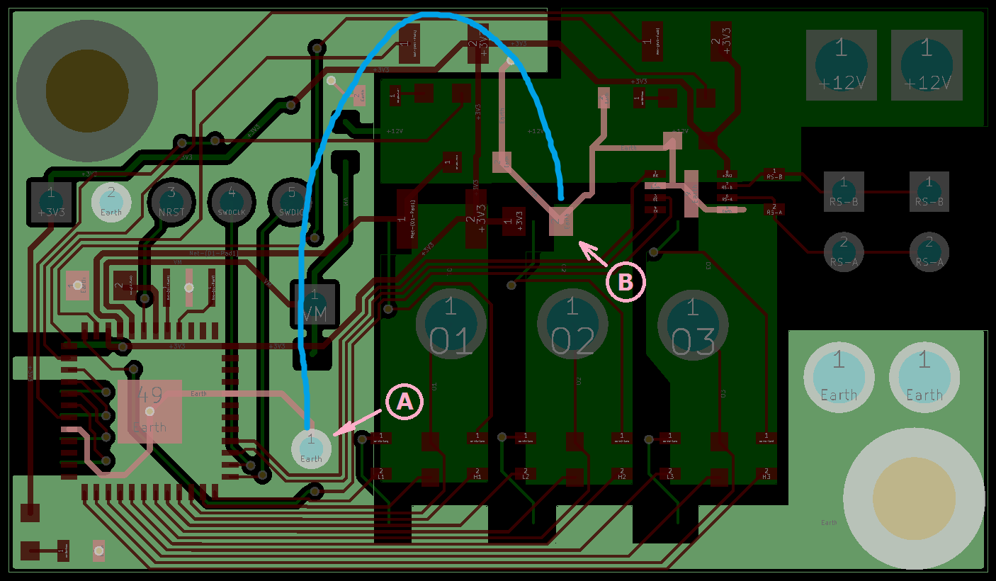
Interestingly, if I connect these two points by soldering a thick wire like this, it does not change scope readings at all
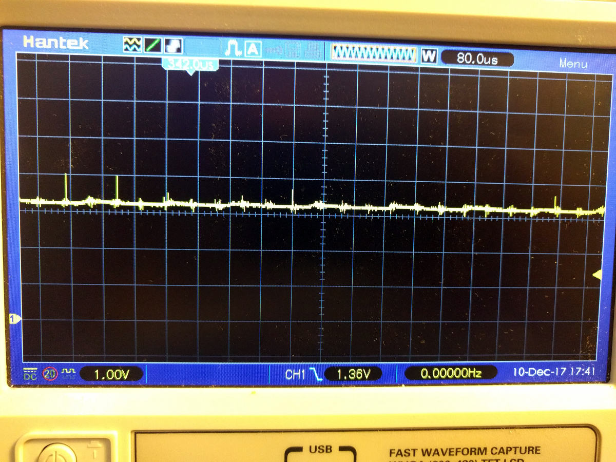
Between ground and 3.3V I see this:
 |
 |
 |
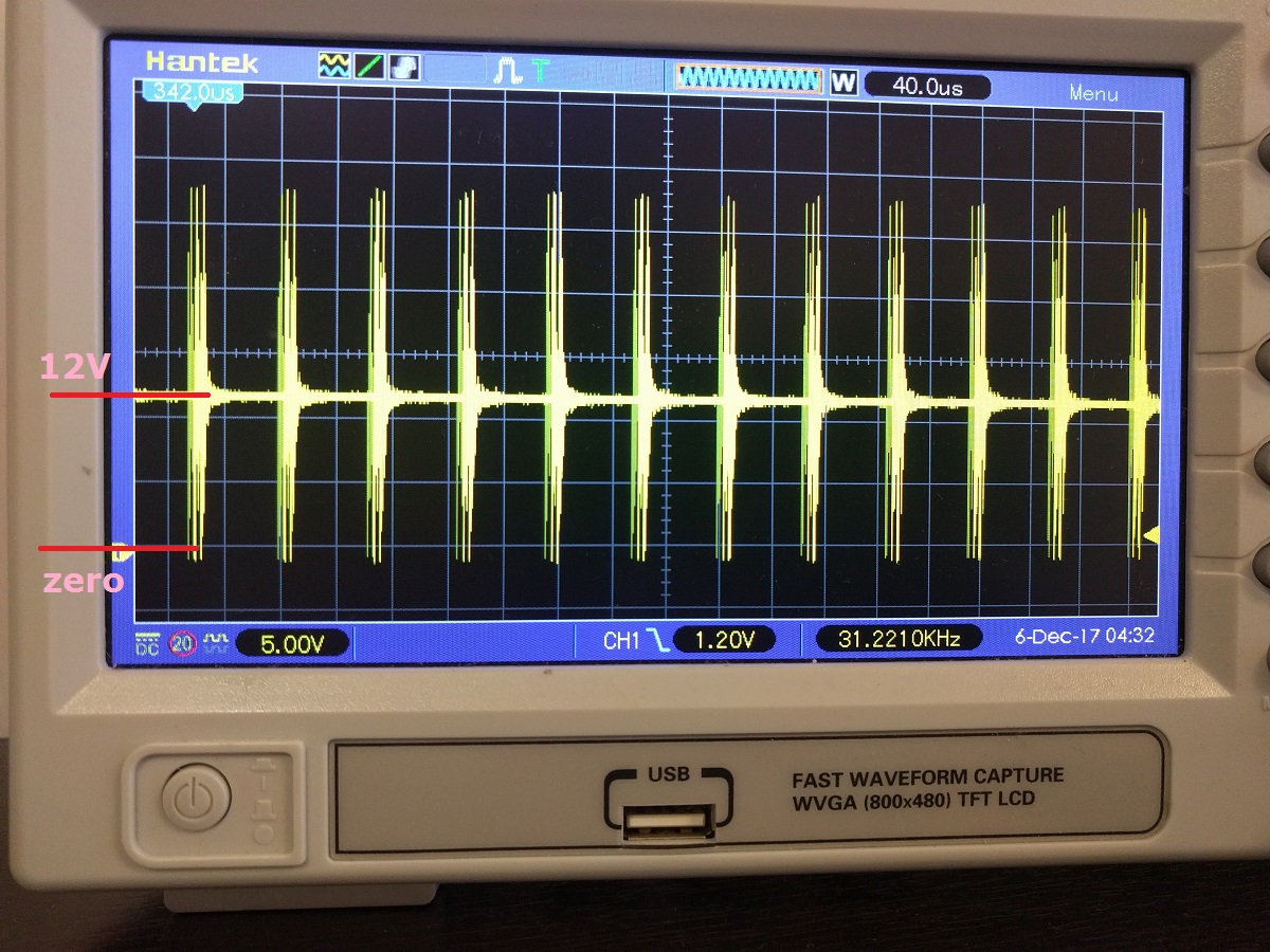
Then I was wondering what 12V supply looks like. Instead of steady 12V I see… well… this 🙂
 |
 |
And this was just 20% of the power. What will I see at 100% god knows!
Interestingly on the other side of diode it is nice and steady, however much higher than 12V:
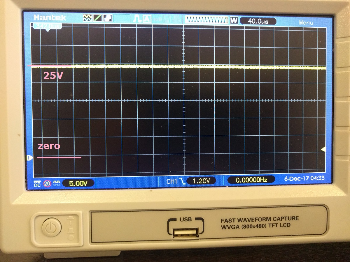 |
 |
Then I tried my old borad
I was thinking I get this effect from hi-current part being on the bottom layer right underneath the logic. So I took one of my old experimental boards that has it all in one layer with hi-current switches on the side.
I prepared aluminium foil covered with sticky tape.
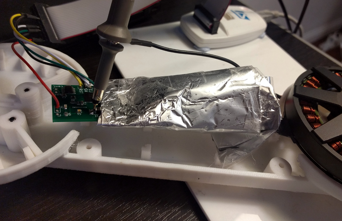
I wrapped the high-current part of the board
Then between ground and 3.3V I saw this
| Wrapped | Unwrapped |
 |
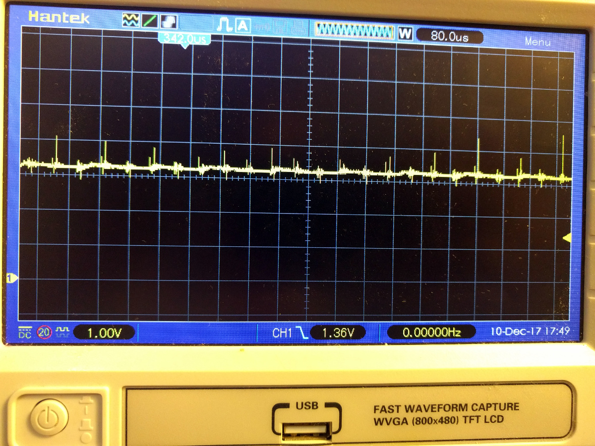 |
A very slight improvement can be seen, still very far from solving the problem.
So now my question is…
What should I change in my design to achieve stable ground and 3v3? Any comments will be appreciated and if I manage to resolve the problem I will post the solution.